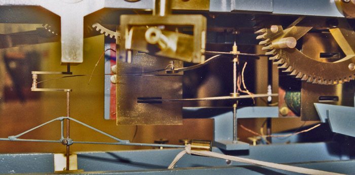
The clock worked as a master/slave system with the master pendulum and power source, in the basement of the house, driving the slave unit in the church tower. The master unit was removed decades ago and no information about it remains. However, other such mechanisms used an electrical impulse to keep the pendulum going. As the pendulum swung it switched the current to the slave coils, which are at the bottom of the clock mechanism. The accompanying diagram shows the general arrangement and the photo below shows this in the clock mechanism.
A pulse was sent every two seconds to repel the armatures out of the coils. This tugged on a wire which pulled the crank on the rotating spindle which is connected to the clock. Thus converting the regular oscillatory motion into a regular rotating one. The weights on the ends of the rotating arms maintained the momentum between pulses.
In the period between the timing pulses another of reverse polarity was sent to draw the armatures back into the coils. Thus the master unit had to send reverse pulses for each swing of the pendulum. Considering also that the house and church are well over 100 metres apart this must have been a significant electrical current to successfully transfer that distance given the quality of cables at that time.
How long the clock operated for is unknown. Access to the tower for maintenance was very difficult, which is perhaps one reason why an electric system was chosen. However, the batteries for the motors would have needed to be replaced and the mechanism would have needed some attention like any other mechanical device.